Strength of materials
Ritter's method
- What is the Ritter method? - principles and application
- Principles of the Ritter method
- Computational example with commentary
- Step 1 - numbering of bars and designations
- Step 2 - calculation of support reactions
- Step 3 - Ritter's intersections
- Step 5 - completion of the solution
- Step 6 - final normal force diagram
- Video - solution using the Ritter method
From this text, you will learn more about the Ritter Method and you will find examples of solutions for trusses using this method.
What is the Ritter Method?
We will explain the Ritter Method immediately with a computational example with extensive commentary. Before we start learning the Ritter Method, it is worth knowing the Zero-Force Member Theorem. If you are interested in the method of joint equilibrium <- koniecznie zajrzyj tutaj.
The Ritter Method involves making mental cuts through the members of the truss (also known as the method of cuts), in order to mentally separate it into two parts, then we discard one side and write the equations of static equilibrium for the other side. At the locations of the cut members we insert axial forces, which can be denoted, for example, as "N" or "S" with the appropriate subscript to describe which member the force is in.
Rules of the Ritter Method:
- if after the cut we have a system of converging forces (i.e., when all unknowns intersect at one point) we have two equations of equilibrium (the sum of projections on the "x" axis and on the "y" axis) and we can calculate two unknowns of forces in the members,
- if after the cut the unknown forces in the members do not intersect at one point, we have three equations of equilibrium and we can calculate three unknowns.
Computational Example with Commentary
Content
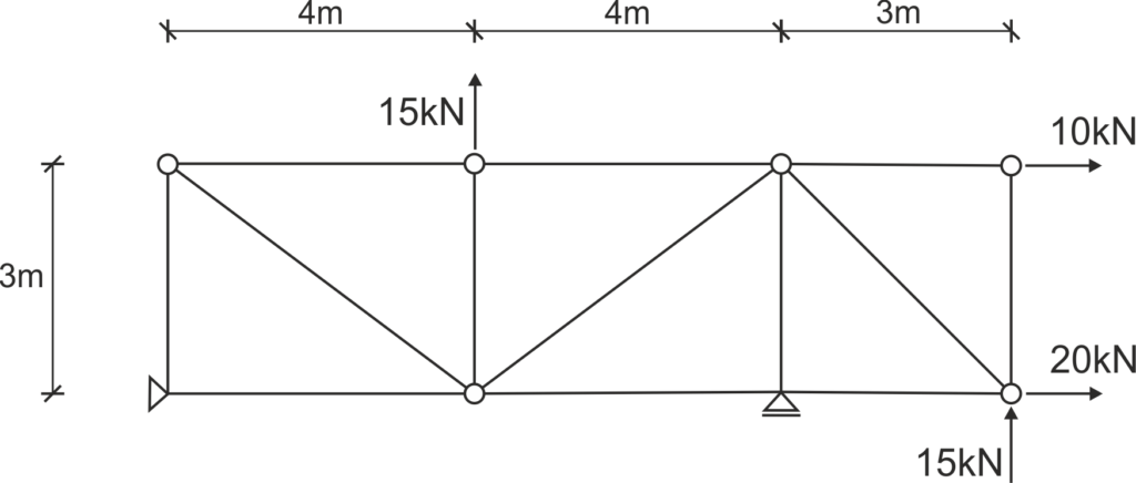
For the given truss, identify the zero-force members and determine the forces in all members using the Ritter Method.
Solution
Step 1
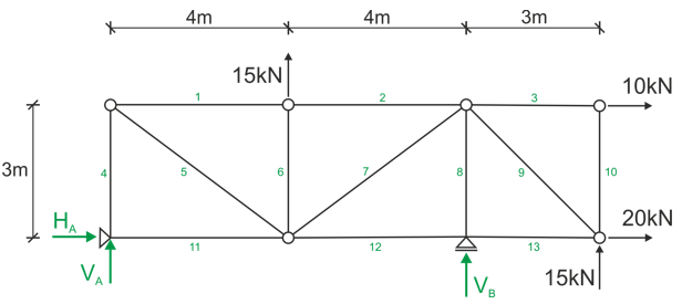
Number the members, optionally label the joints, and indicate the support reactions.
Step 2
Write the equations of static equilibrium and calculate the support reactions.

Step 3
We make Ritter cuts.
We can start in any way, as long as we do not cut through more than 3 members, because that is the number of unknowns we can calculate in one cut.
Let's start by cutting through members 2, 7, and 12 and make a view from the left side
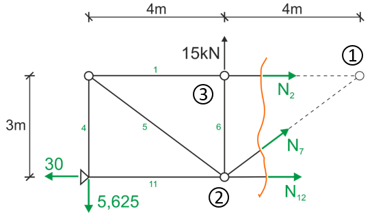
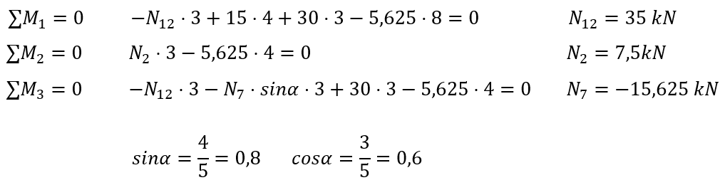
We write the equations of static equilibrium
The so-called Ritter points are the points where the directions of two unknowns intersect.
In the figure above forces N2 and N7 intersect at point (1) and forces N7 and N12 intersect at point (2) - these are the Ritter points. Most often, we write the sums of moments at the Ritter points; it happens that there are more than two such points if the forces are at different angles, then we can write three equations in the form of sums of moments.
If, however, we only have two Ritter points as here, that is fine; we write two sums of moments and as a third equation we can write either the sum of projections on the "x" axis or (better) on the "y" axis, because only the unknown N7 enters this equation.
We can also write the sum of moments at another point, so as to calculate the last unknown, here point (3) was determined.
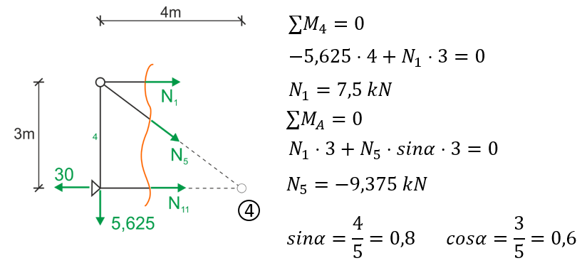
Similarly, we do the Ritter cut through members 1, 5, and 11
View from the left side
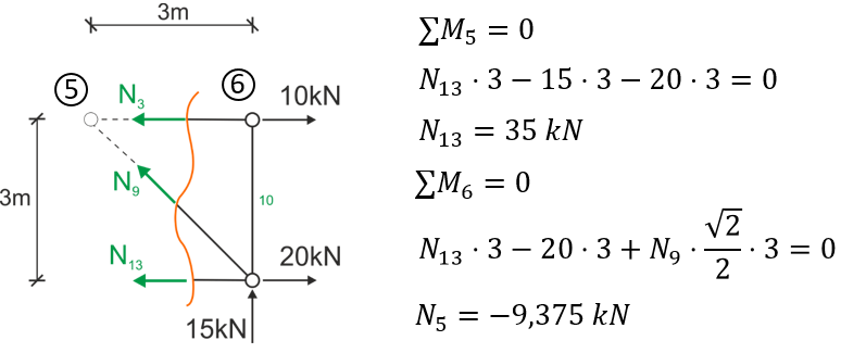
The last will be the Ritter cut through members 3, 9, and 13
View from the right side
Step 5
Complete the solution to the problem.
Let's draw the diagram of normal forces in the members that we have already calculated.
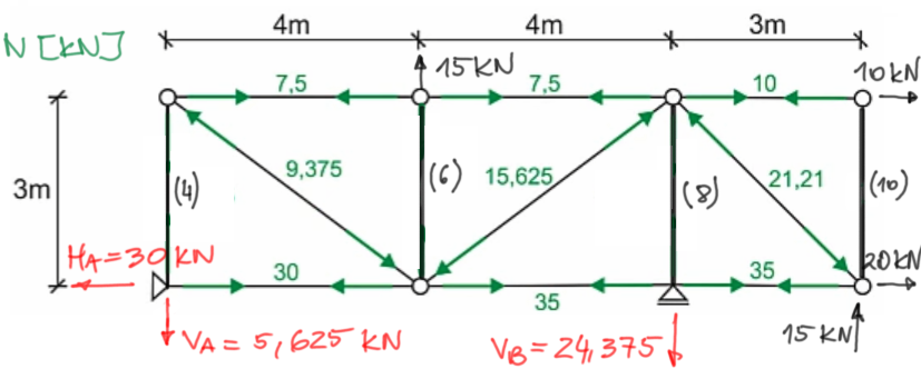
Diagram of normal forces, labeling:
POSITIVE

NEGATIVE

- make additional cuts, but we need four separate cuts to calculate these forces, which somewhat defeats the purpose.
- make equilibrium at joints A, B, (3-10) and (1-2-6) and add the last four forces, it will definitely involve less drawing by cutting a single joint than making a larger cut,
- cleverly notice, that:
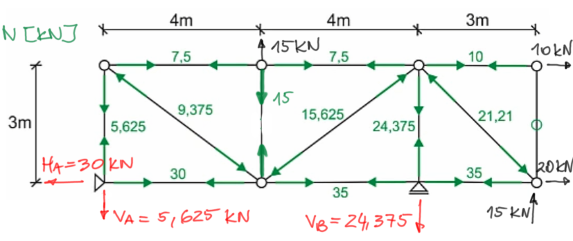
1) from the second theorem on zero-force members, member (10) is zero,
2) from the second theorem, it essentially follows an additional principle - if a force loads a joint in such a way that its direction is collinear with one of the members and no other force can be projected onto that line, then the force in the member is transmitted collinearly.
Let's look at the bottom chord and joint B - the force of 35kN in the horizontal member transfers from member to member as shown in the diagram, while the reaction VB=24,375 kN loads collinearly member (8) - thus directly transmitting the tensile force to it (because we see that the reaction VB acts on member (8) in such a way that it stretches it).
ultimately, from this we know the force in member (8)
3) on the same principle N6=15 kN
4) on the same principle N4=5.625 kN
Step 6
We draw the final diagram of normal forces.
Video - solution using the Ritter Method
The same in video format with a more detailed description of the entire equations and individual steps.