Strength of materials
Types of supports in the plane and in 3D space
- what is a support in structural mechanics
- what are the degrees of freedom of movement in the plane
- what are the types of supports in the plane
- sliding hinge support
- fixed hinge support
- truss member/tension cable/rope
- full fixation/bracket
- fixation with displacement/sliding block
- rotation lock/wedge
- what are the degrees of freedom of movement in 3D space
- what are the types of supports in 3D space in systems such as:
- hinged frames
- rigid frames
- 3D frames
What is a support in structural mechanics?
A support in structural mechanics is an element that provides a reaction to forces and moments acting on a structure or construction. In the context of engineering and structural design, supports are essential components that allow for load transfer, ensure stability and balance of the structure, and enable it to function safely and efficiently.
The number of independent movements that an object can perform on a plane
Different types of supports restrict different possibilities of movement on a plane or in space.
On a plane, there are three main degrees of freedom of movement:
- Translation along the X-axis: This is movement along the horizontal X-axis, allowing the object to move left or right on the plane.
- Translation along the Y-axis: This is movement along the vertical Y-axis, allowing the object to move up or down on the plane.
- Rotation around the vertical axis (Z): This is the movement of the object rotating around the axis perpendicular to the plane, commonly referred to as the Z-axis. This movement allows the object to rotate around the center of the plane.
It is worth noting that degrees of freedom may vary depending on the context and specifics of the construction. For example, the degrees of freedom of a complex mechanism may include additional movements such as tilting or rotation around other axes.
In the case of analyzing the movement of objects on a plane, these three basic degrees of freedom serve as a key reference point.
Types of supports on a plane
Given that on a plane we have three degrees of freedom of movement, supports can restrict these degrees of freedom in various combinations. [[PROTECTED_131_HTML ]]The removal of a movement possibility such as horizontal is associated with the generation of a reaction in that direction. First, we will briefly characterize the types of supports on a plane, and then for clarity, we will compile the following information regarding supports on a plane in a table:
- popular name(s),
- graphic symbol(s),
- what reaction occurs in it,
- which degree of freedom of movement it removes.
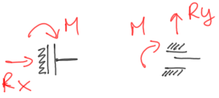
a) sliding hinge support
Blocks linear movement in one direction, allows movement in the direction perpendicular to the blocked one, and allows rotation. The graphic symbols encountered in the literature are:
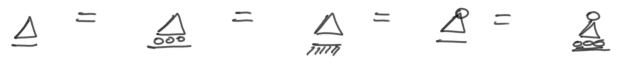
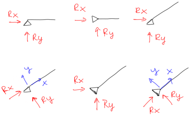
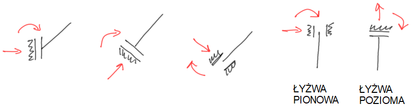
The horizontal line under the triangular symbol of the hinge support shows the direction in which there is the possibility of movement. The direction perpendicular to the possibility of movement is blocked, and in that direction, a reaction occurs. Of course, the sliding hinge support can be used at various angles, as shown below:

If the support and the reaction are at an angle, it is often more convenient for simplification of calculations to decompose this reaction into components:

After decomposition into components in calculations we use either one, resultant reaction (red) or both components (blue) – never both at the same time. This means that when writing the static equilibrium equation or determining internal forces, we use either the components or the resultant reaction.
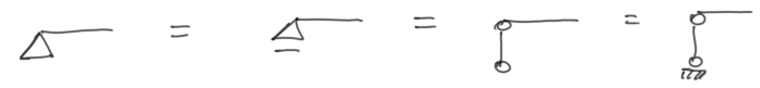
b) non-sliding hinge support
In a non-sliding hinge support, there is also actually one reaction, however we do not know its direction. Therefore, it is best to immediately indicate two components of this reaction. They do not have to be necessarily vertical and horizontal, but must be perpendicular to each other. It is also worth mentioning that the directions of the reactions never matter and are only a matter of our assumption. In the illustration below, in addition to the symbol of the support, a rod (of course, it does not matter at what angle the rod exits the support) is marked

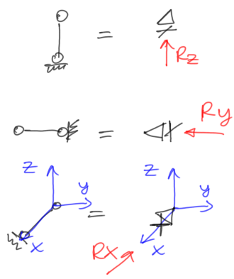
Note! If the outgoing rod is additionally terminated with a hinge on the other side, then we are dealing with a truss member/tension/rope of which more information can be found below.
Often the dilemma regarding the marking of the reaction arises when we see a non-sliding support rotated at various angles. It should be remembered that in such a support we always have two perpendicular reactions, and it is up to us to decide in which directions these reactions are marked. Each variant shown below is OK.
c) truss member/tension/rope
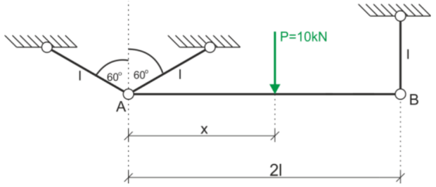
We may encounter such a support for a beam/frame – non-sliding hinge support + attachment with a rope (See free example 1)

or with the beam attached only by ropes. (See free example 2)
For us to speak of a rope/tension/truss member the following assumptions must be met:
- the member must be terminated on both sides with hinges (these are the nodes of the member),
- the member must be linear (it cannot have bends, see the example below),
- there cannot be any load between the nodes,
- the load can be applied only at the node (keeping in mind that if it is a concentrated moment, it cannot be applied strictly at the hinge, it must be applied from one side or the other of the hinge)
A truss member is primarily characterized by the fact that:
- it only has axial (normal) force,[ [PROTECTED_284_HTML]]
- it does not have shear forces and bending moments.
Below on the left is an example of two truss members, on the right due to the lack of a hinge in the middle the member is not linear, so we do not have a truss member but a framework system supported by two non-sliding hinge supports.

This is a fundamental difference between these two constructions, and they are calculated quite differently. In hinge supports, we show reactions as previously demonstrated, while for reactions in a truss member, we have two options for marking the reactions
- Intersection of the member and showing internal forces in the member (axial) and rejecting the parts outside the structure
- Showing the reaction at the end of the member, outside the structure, that is at the support; the reaction occurs only along the axis of the member

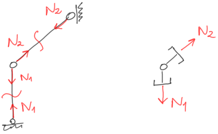
On our site, you will find rather this first variant, as we find it better
In the case above:
- we cut through the member,[ [PROTECTED_328_HTML]]
- show forces in the member (always either towards each other or away from each other – it is best to assume as above, that is towards each other – then we assume that the member is being stretched),
- rejecting those parts outside the structure.
d) fixed support/bracket
A fixed support, or commonly known as a bracket, removes all possibilities of movement on the plane, thus the possibility of linear movement and the possibility of rotation. It therefore has three reactions, two perpendicular reactions in the form of concentrated forces and a concentrated bending moment. Just like in the case of a non-sliding hinge support the directions and orientations of the reactions are a matter of our assumption (we just remember that the concentrated reactions must be perpendicular to each other).

e) fixed support with sliding/roller
A fixed support with sliding allows linear movement in one direction, while simultaneously blocking linear movement in the perpendicular direction and rotation. We can distinguish between vertical and horizontal, but the fixed support with sliding can just as well be at any angle, below are several possibilities for marking the roller along with the reactions in it.
f) rotation lock/wedge
This is a type of support that is very rarely encountered and is not strictly applied in the task topic, but we can most often encounter it when solving a beam/frame using the principle of virtual work and of course we deal with it in almost every problem in the field of structural mechanics – displacement methods.
A rotation lock is a tie that locks, as the name suggests, only the possibility of rotation of a point (node). We may encounter such markings of rotation lock:

In this support there is only a reaction in the form of a bending moment, the node has freedom of movement in every direction, but cannot rotate – meaning the shape of the node after displacement must be the same as before displacement. The first graphic marking on the left resembles a wedge, and we may also encounter this name for this tie. The third marking resembles a roller both vertically and horizontally.
Degrees of freedom of movement in 3D space
In three-dimensional space (3D) there are six main degrees of freedom of movement, which determine the number of independent movements that an object can perform. Here are these degrees of freedom:
- Translation along the X-axis,
- Translation along the Y-axis,
- Translation along the Z-axis,
- Rotation around the X-axis,
- Rotation around the Y-axis,
- Rotation around the Z-axis.
All these degrees of freedom together define how an object can move and rotate in 3D space. Thanks to this classification, engineers and designers are able to analyze and model the movements of objects and structures in three dimensions.
Types of supports in 3D space
In a planar system having 3 degrees of freedom of movement (translation X, translation Y, rotation Z) we have managed to specify 6 types of supports depending on the combinations in which the supports removed the allowable degrees of freedom of movement.
It will be difficult to classify supports in 3D space, therefore we will provide below rather general principles regarding supports and the most popular supports in constructions such as:
- hinged frames,
- rigid frames,
- 3D frames.
A frame is defined as a planar rod structure, which is loaded perpendicular to the plane of the frame beams. Due to the way the beams of the frame are connected, we can distinguish:
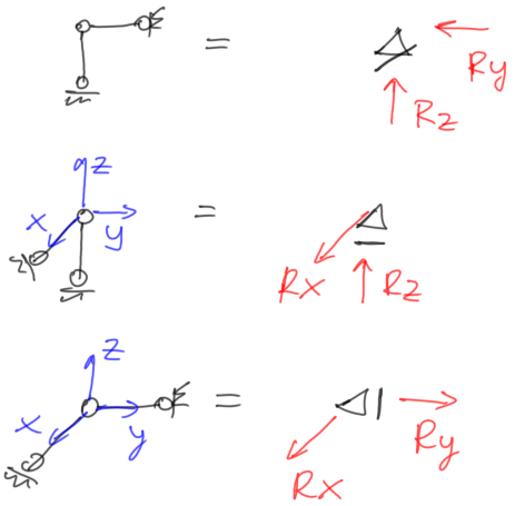
a) hinged frames
The beams of the frame are connected to each other with hinges, in a way that allows them to freely rotate relative to each other. Such a connection allows only for the transfer of vertical (perpendicular to the plane of the frame beams) forces through the lever arm connecting the beams.
Since the load on the frame acts in a direction perpendicular to the plane of the beams and because the beams only transmit transverse force to each other, in a hinged frame, there are only transverse forces and bending moments. This affects what reactions can occur in the supports, and we can distinguish supports such as:
- hinge support
Where it does not matter whether it is drawn as sliding or not – we do not mark reactions in the plane of the frame, only the reaction from the plane.

- vertical roller
Below is a vertical roller marked in two directions along with the reaction in the form of a moment – which is marked in two ways – as a moment vector and as a moment on a "note" – both notations are equivalent. In the roller, there is no vertical reaction, in frames we generally omit reactions along the axis of the beams, so here we only have a reaction in the form of a moment – and it is a bending moment for the member, as hinged frames do not transmit twisting (due to the hinge connections).

- fixed support
In a fixed support with a hinged frame, we have a reaction in the form of a bending moment for the beam and a vertical force. Below, the reaction in the form of a moment is marked in one drawing in two ways

Solutions to problems with hinged frames can be found in the online course structural mechanics – specifically here, they are covered by a subscription (one subscription provides access to materials across the entire site – i.e., to all online courses).
b) rigid frames
The beams of the frame are connected to each other rigidly (you can imagine it as if the members were embedded one in the other). Bending of members arranged in one direction causes bending and twisting of members in the other direction.
In rigid frames, we have the same supports as in hinged frames, however, the difference here is that we also deal with twisting, so in a fixed support in addition to the reaction in the form of a bending moment there will also be a reaction in the form of a twisting moment. We will also have more roller options (either blocking bending, or twisting, or both).
Types of supports in rigid frames:
- hinge support
Exactly the same as in a hinged frame. It does not matter whether it is drawn as sliding or not – we do not mark reactions in the plane of the frame, only the reaction from the plane.
- vertical roller
As mentioned earlier, we have three types of rollers in a rigid frame:
- with a reaction in the form of a twisting moment,[ [PROTECTED_562_HTML]]
- with a reaction in the form of a bending moment,[ [PROTECTED_564_HTML]]
- with both of the above mentioned.

Well, the first marking can often be used as a fixed support, so it is best to clarify if possible what type of support the person drawing the task has in mind.
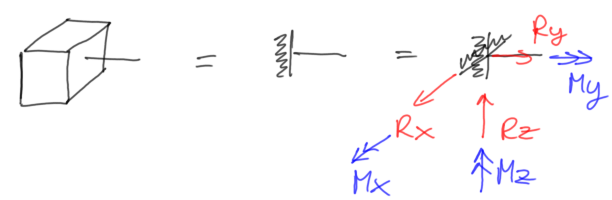
- fixed support
If we wanted to consistently apply a marking similar to that of the roller, we should mark the fixed support in the way shown on the left, however, I think that the most popular will still be the simplest marking we encountered earlier – presented on the right

c) 3D frames
In a spatial frame, we have 6 ties, so the reactions can receive these ties in various configurations. Most often, we will deal with fixed supports and ordinary support members that block movement in the direction in which the member is placed.
Below are several possibilities for supports:- support member/sliding hinge support
In one place, there can be one, two, or three directions blocked, so now a variant with two blocks in one place
- support members/sliding hinge support
- non-sliding hinge support

- fixed support
You are unlikely to encounter any other type of support than those mentioned above in spatial systems (I have not encountered it), generally, as a rule, any direction of linear movement and the possibility of rotation can also be blocked in any combination, for example

and similar.