Materials strength
How to check the equilibrium of a joint in a frame
- What is node equilibrium? - definition and application
- Examples of checking node equilibrium
- Example 1 - equilibrium of a rectangular node
- Example 2 - equilibrium of a node with an inclined rod
What is node equilibrium?
A node is a point in the frame where two or more bars connect. Having drawn the internal force diagrams for the frame, we can assess their correctness by performing a check of the node equilibrium.
This involves reading from the diagrams the values and directions of the normal force, shear force, and bending moment from each side of the node and checking whether the static equilibrium equations are satisfied for the internal forces read in this way - the sum of the projections of the forces on the x and y axes and the sum of the moments must equal zero.
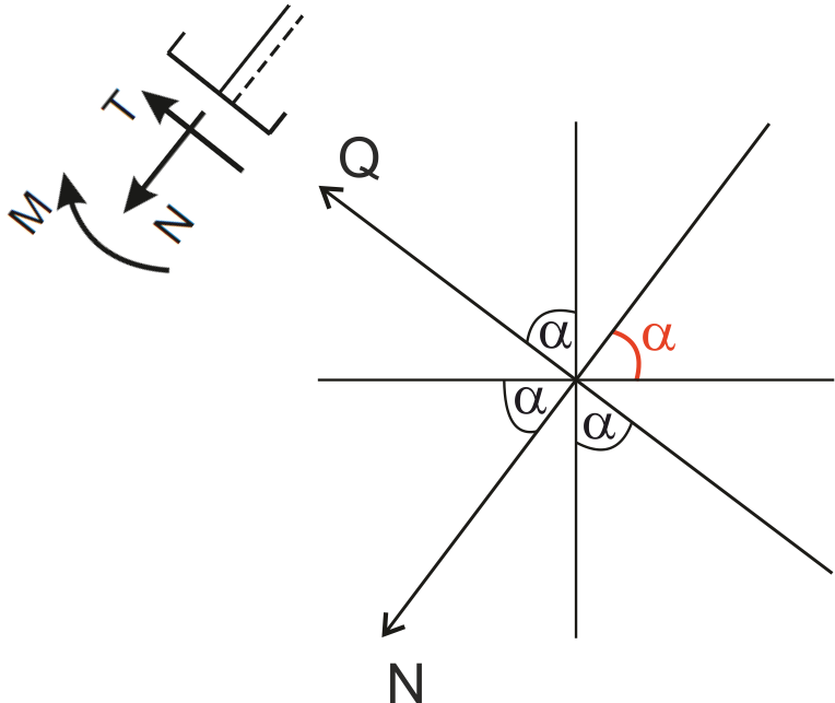
The first thing we need to do is correctly read the forces from the diagrams, we must remember the sign convention:
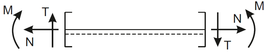
Next, if a diagonal bar is coming into the node, we need to be able to project the forces at an angle onto horizontal and vertical components.
We will show an example with a diagonal bar later, but now let’s see what the equilibrium check for a rectangular frame will look like.
To check the equilibrium of the node, we obviously need to have the internal force diagrams drawn; we will not go through the drawing of the diagrams. If you want to practice this topic, refer to the introduction regarding internal forces in frames.
Below are links to the task database, and below them two examples of node equilibrium.
Example 1 - equilibrium of a rectangular node
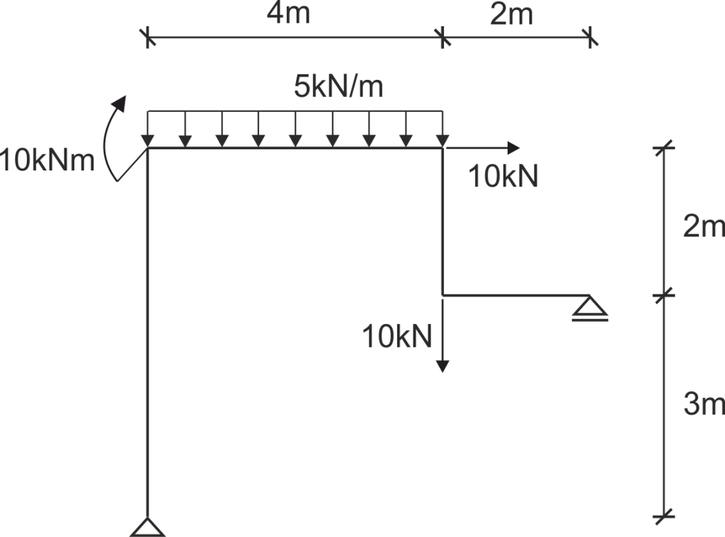
This is one of the examples from our solution database, to which links are provided above.
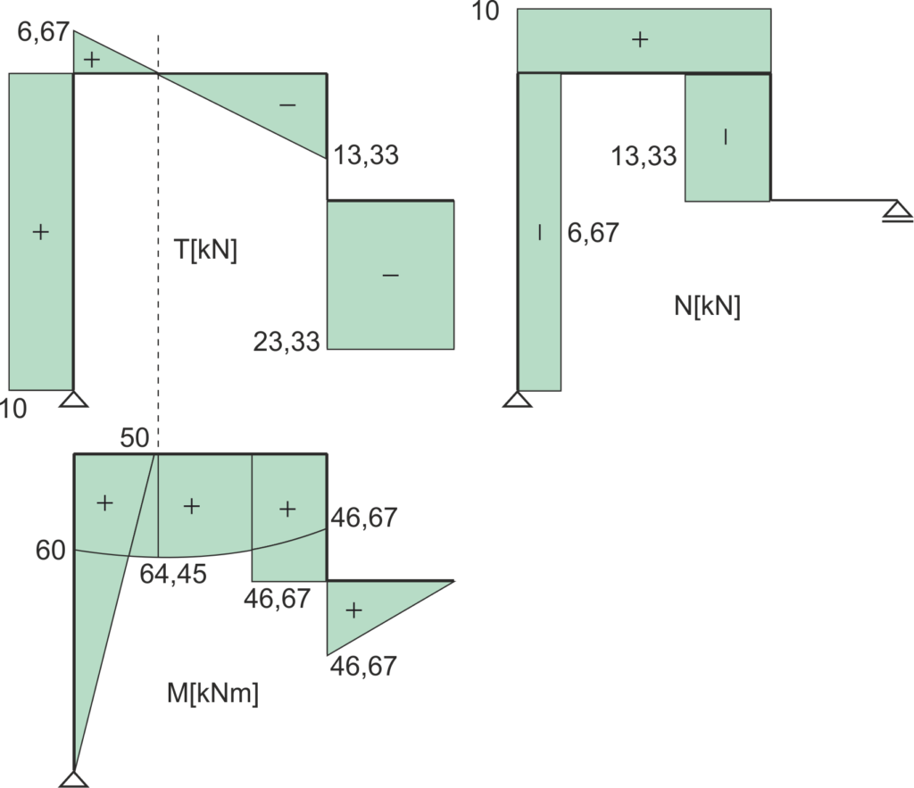
For this example, the internal force diagrams have been drawn as shown below:
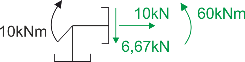
Let’s check the equilibrium of the node to which a concentrated moment of 10 kNm is applied.
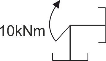
It is worth noting that we cut the point - the node, cutting through the bars approaching the node infinitely close to the node, so we do not see the continuous load from the horizontal bar.
On the right side of this node, looking at the diagrams, we have forces: shear +6.67 kN, normal +10 kN, bending moment +60 kNm.
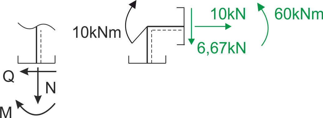
We look at the sign convention, the view from the right side - there the directions of the positive internal forces are marked, in the analyzed diagram all forces are positive, so they have the same directions as in the sign convention above (view from the right side).
As for the vertical bar, it is good to assume from the right or left side of the bar "bottom" (meaning the assumed bottom of the bar), to simplify the use of the sign convention, which also marks the bottoms (at the bottom).
Let’s assume the bottoms are on the right side of the vertical bar - and now we have two possibilities - either we rotate the vertical bar so that we have the bottoms at the bottom, then we have such a cross-section when cutting the node that we look from the left side.
Or we rotate the sign convention to match the assumed bottoms (that is, counterclockwise by 90 degrees) - and I will show this version below.
For the assumed bottoms, we see what directions the normal force, shear force, and moment are positive. In the diagram above, below the node we are analyzing, we have: normal force -6.67 kN, shear force +10 kN, bending moment +50 kNm.
We therefore mark these forces under the cross-section with the appropriate directions; for the normal force, which is negative, the direction is opposite to that in the sign convention, while for the shear force and bending moment, the directions are consistent with the convention.
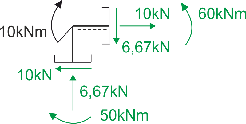
Now we write the static equilibrium equations:
\begin{aligned} & \Sigma \mathrm{x}=0 \\ & -10+10=0 \\ & 0=0 \\ \\ & \Sigma \mathrm{y}=0 \\ & -6.67+6.67=0 \\ & 0=0 \\ \\ & \Sigma \mathrm{M}=0 \\ & 50-60+10=0 \\ & 0=0 \\ \end{aligned}The check gives a positive result.
Example 2 - equilibrium of a node with a diagonal bar
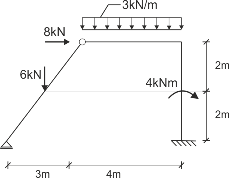
You can find the complete solution to this example in the introduction regarding internal forces in frames.
Internal force diagrams


Checking the equilibrium of the node with a diagonal bar
The moments at the node have zeroed out (joint), so we have no moments here, we have shear and normal forces - we read them from the drawn diagrams above.
We remember the sign convention, looking from the right side of node C on the normal force diagram we have a force of -8 kN, the minus indicates that it is compression, so we mark the force at the node from the right side with the appropriate direction.
On the shear force diagram from the right side at the very node, we have -3 kN, looking from the right side, positive shear forces have a downward direction, so we mark the negative force with an upward direction.
In the same way, we read the directions and values of the forces from the diagonal bar. If we assume the bottoms inside the frame, we need to rotate the sign convention counterclockwise by a certain angle to match it to the diagonal bar, looking from the left side at the sign convention we see how the positive normal and shear forces are directed from that side.
In the diagram, we have a shear force of -3 kN and a normal force of +2.4 kN. This is what the cut node looks like with the read cross-sectional forces:

| \( \quad \quad \) |
Static equilibrium equations \begin{aligned} &\Sigma X = 0\\ &8 - 8 - 2.4 \cdot \cos (\alpha) + 1.8 \cdot \sin (\alpha) = 0\\ &L = P\\ &\Sigma Y = 0\\ &3 - 2.4 \cdot \sin (\alpha) + 1.8 \cdot \cos (\alpha) = 0\\ &L = P \end{aligned} |
We need to project the forces from the direction of the bar axis (normal force on the bar) onto the horizontal and vertical directions. We also need to project the shear force.
| \( \quad \quad \) |
When it comes to projecting forces onto components, a good idea is to draw a "web" - make a drawing on which we will mark the vertical direction, horizontal direction, the bar axis (normal direction), and perpendicular to the bar axis (shear direction). The angle alpha is taken by looking at the frame between the level and the bar axis. Additionally, you can mark the direction of the positive normal force and the positive shear force, which applies from the side from which we are looking. |
We use the web with marked angles alpha - we apply the force to the web drawing, we draw the two nearest components, we see where the angle alpha is.
The component at which the angle alpha is marked is multiplied by the cosine of that angle, and the other by the sine of that angle.
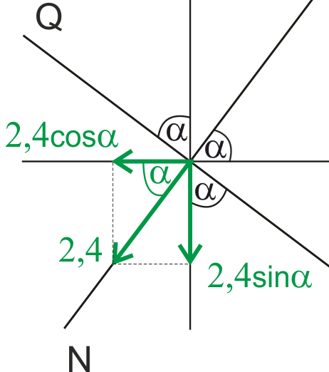
| \( \quad \quad \) |
For example, to project the normal force onto components, we could draw it as shown in the adjacent drawing. |
That's all, good luck with checking the equilibrium of nodes in frames!
Below you will also find links to numerous solution examples for both simple frames and those with diagonal bars, as well as frames with joints.